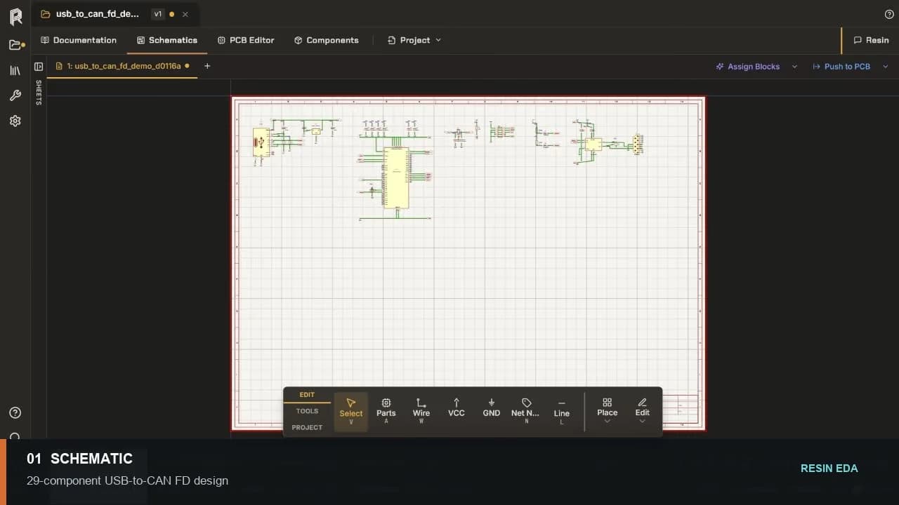
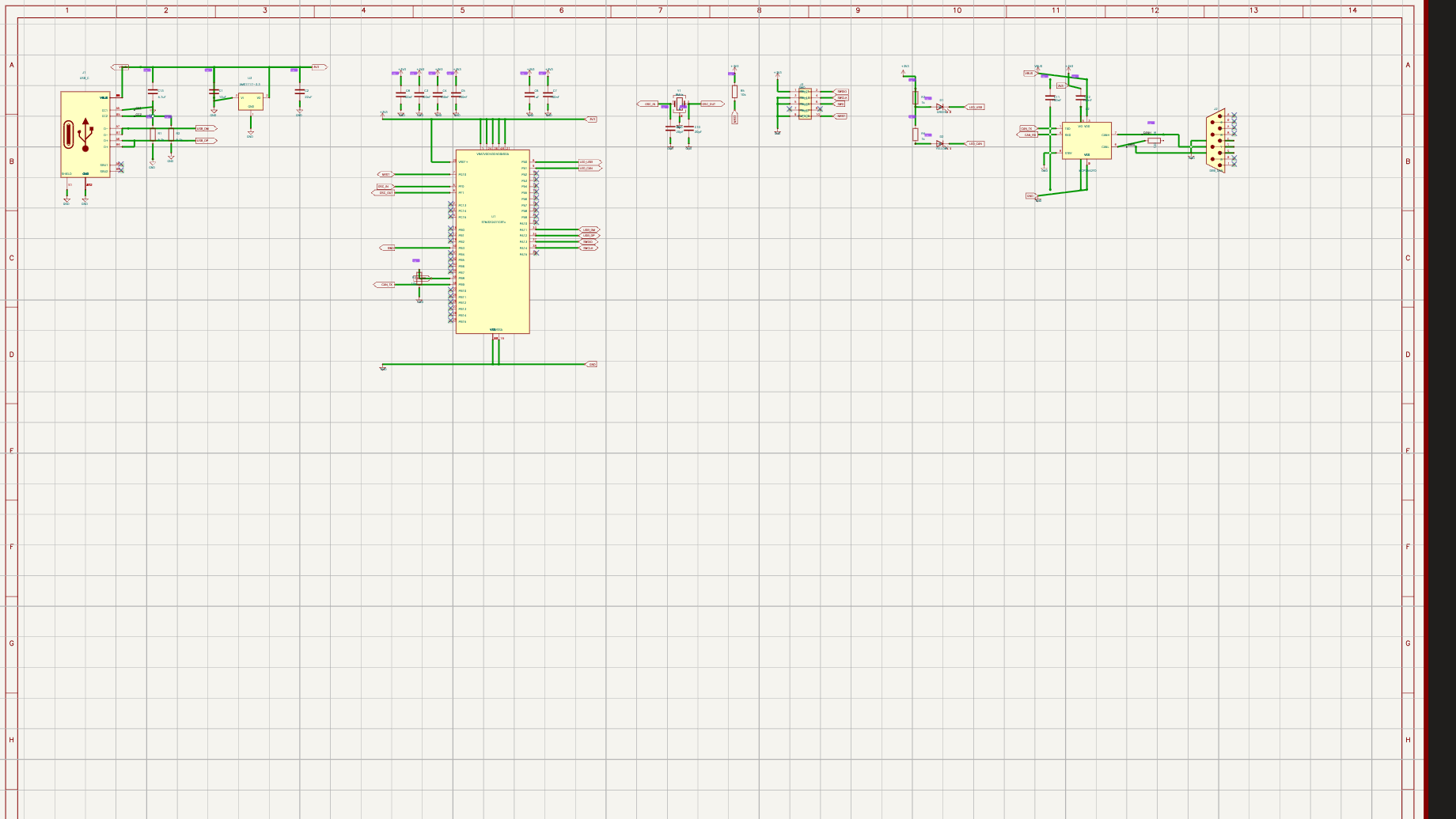
USB-to-CAN FD project / schematic through outputs
Move from circuit idea to manufacturing files in one browser. Start a new board or bring in an existing design, then edit the schematic and PCB, run review and checks, and prepare the release package.
No credit card required.
New-board sequence
From editable schematic to manufacturing files. The stages below show the input, engineering action, check, and output for a typical board-design path. Resin AI can assist, but the schematic, PCB, and review decisions remain visible to the engineer.
Checked Product captures / July 2026
Context USB-to-CAN FD example project 01 Define and edit the circuit Input: requirements or an existing schematic. Output: an editable circuit with parts, nets, and properties.
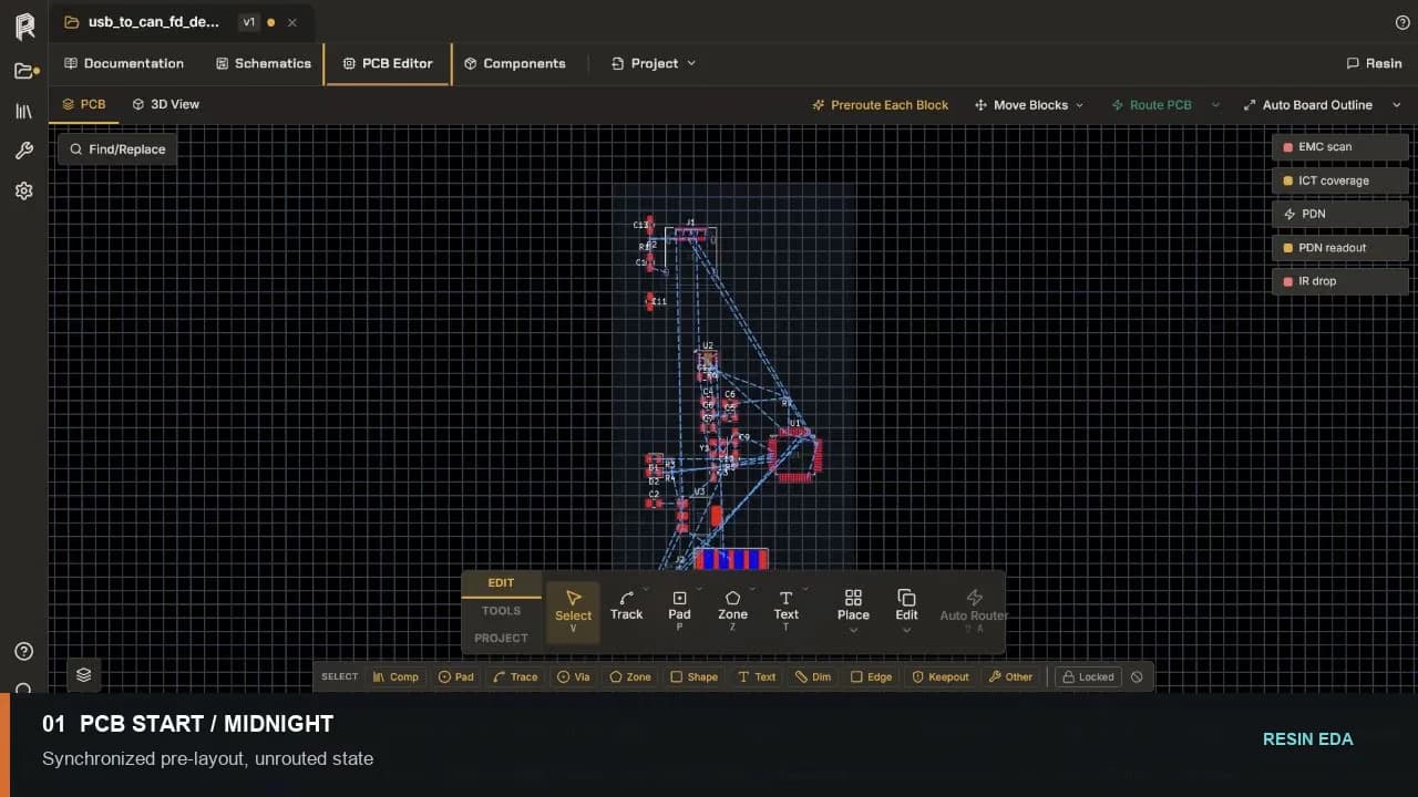
New-board workflow 02 Lay out the physical board Input: synchronized footprints and nets. Output: placed and routed copper that remains directly editable.
PCB design tools 03 Run review and checks Input: the intended revision and rule set. Output: AI review, ERC, and DRC findings tied to the design.
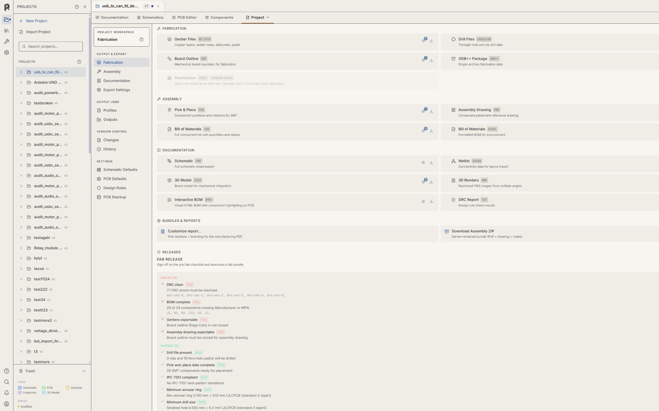
Design-review workflow 04 Prepare the release package Input: the reviewed board and assembly variant. Output: configured fabrication and assembly exports.
Release workflow Inputs New board requirements A supported existing project The revision and constraints under review Outputs Editable schematic and PCB Recorded review and check results Configured manufacturing exports Known limits AI-assisted work still requires engineering review Output controls do not prove a package has been accepted by a manufacturer 01 Start from requirements
Design a new board Define the circuit, edit the schematic, synchronize the PCB, place and route the board, run checks, and prepare outputs.
Open the new-board workflow 02 Start from existing files
Import an existing design Pilot a supported source project, compare engineering objects, test a controlled edit, and verify the downstream files your team needs.
Open the import workflow 03 Start from a revision
Review a design change Set the review scope, run AI Review plus ERC and DRC, correct source objects, and rerun the same checks.
Open the review workflow 04 Start from a reviewed board
Prepare manufacturing files Choose the board revision and assembly variant, configure the required files, inspect the package, and hand it off with a clear identity.
Open the release workflow Resin EDA
Run this workflow in Resin. Start with a new or imported board and keep every engineering decision visible.
Questions about team access, security review, or purchasing? Write to hello@resineda.com .